Welcome Guest,

I'm glad to connect with you here. This is my official online diary where I scribble my thoughts and experiences as an Architect. Subscribe to this blog if you wish to be notified of every new post I make. It also qualifies you to get a free author's signing of my e-book: 48-Laws-Of-Architectural-Consulting!

Type a Keyword to Search This Blog

PRODUCTION AND INSTALLATION OF DECORATIVE CEMENT SKIRTINGS

posted By : kosi Emmanuel Chukwujindu

Architect: and Skirting Moulders

There are many methods of producing decorative skirting used at the corners of columns, walls,Windows etc.  
There is the traditional plaster-of-Paris skirting made from white P.O.P cement. This is used mostly for suspended ceilings and waist level skirtings within the interior of buildings. This type has the advantage of being lightweight and mouldable into almost any shape or design. The challenge however with this type is that it is not very resistant to water and thus it is seen to depreciate in aesthetics when exposed to prolonged dripings especially when used in exterior locations.

There is however an alternative method; THE USE OF ORDINARY PORTLAND CEMENT moulded to shape and finished with white (or any color)  paint. Skirting made from portland cement are typically resistant to water and last longer than those made from P.O.P cement. It however tends to be limited in versatility of design, due to its heavier weight. it is usually used for window trims, wall edges and fence trims, and other exterior needs etc.

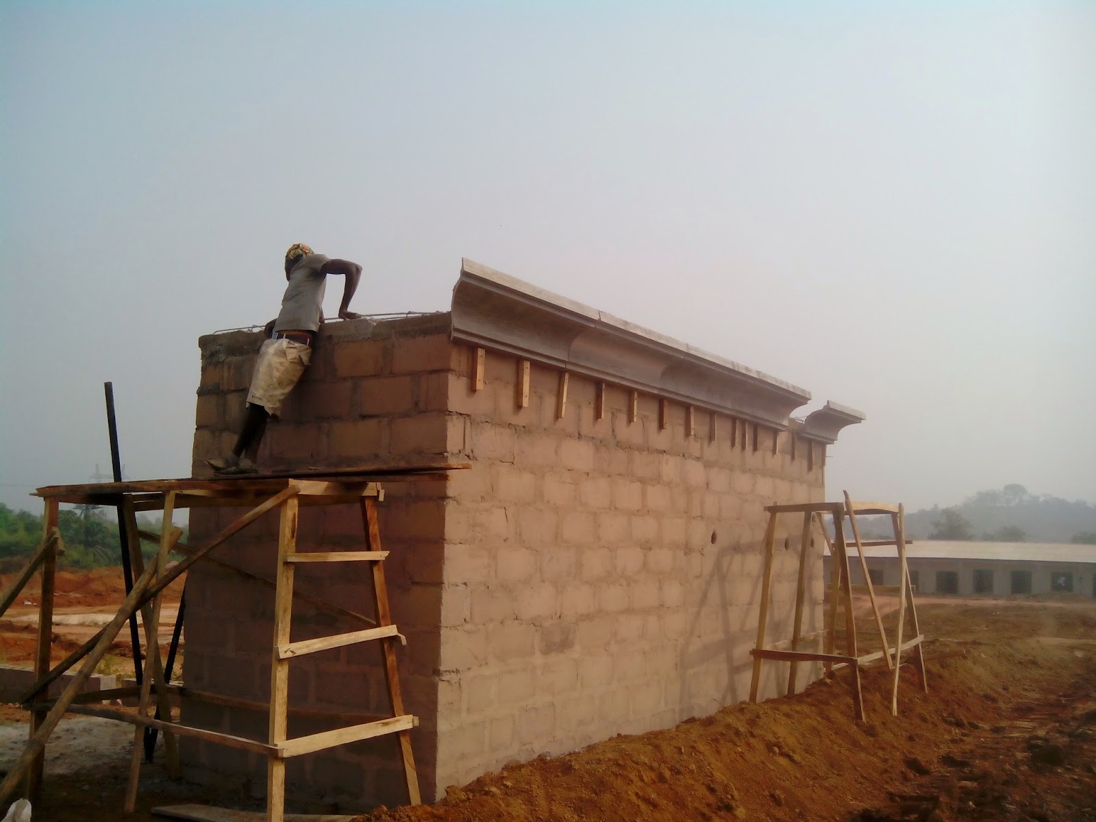
At the ENSIBUM market project, we decided to use skirting made from cement to add some mass to the already gigantic entrance gate. This post is dedicated to describe how we made these skirting in-situ and installed them.

STEP 1: MATERIALS REQUIRED; semi coarse sand, soft texture sand, water, cement, a custom mould. 

STEP 2: PREPARE THE BASE : start by making a mound of about 4ft. length and about 6" high  using the semi-coarse sand. this will serve as base for the skirting, as well as separates it from the ordinary earth after the cement has cured and hence makes it easy to lift and shift. Use two range devices to protect the boundary on both sides of the mound. Using concrete nails to support the ranges along the lenght, making sure the space between them is even all through.  This will provide for a perfect edged skirting in the end.

STEP 3: MIX THE CEMENT: The skirting is made completely of cement mixed with water and a little fine texture sand.( when necessary).  A bag of cement can be properly mixed with about 15 - 20lts. of clean water. it should be stirred properly in a bucket or bowl or any open container that will allow for ease of scooping while molding.

STEP 4: MOULDING :
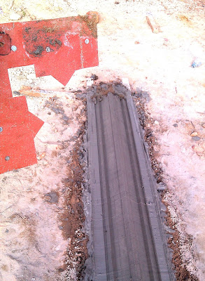
Pour the cement paste gradually onto the sand mound. Use the hand held, locally carved  mould to shape it into desired pattern (as shown here) and allow in same position for at least 12 hours before attempting to remove.
Remember to make nail size openings along the skirting to allow for nailing during installation.

STEP 5: INSTALLATION: 
By physical inspection, you can tell when the skirting is strong enough to be handled without breaking. You can then raise it neatly, and carry to point of fixing. The plumb device is used to mark straight positions along the wall. this is to ensure that the skirting is not slant at any point which will look bad to the viewer.
Nail the skirting onto the wall, siupported by wooden noggins and use cement to dress the edges neatly!


BEFORE CEMENT SKIRTING


AFTER CEMENT SKIRTING

WRITING QUOTATIONS FOR PROJECTS


As an Architect, you will be required to prepare work estimates in form of job quotations for proposed projects. Your ability to predict or forecast real life site requirements from your drawing board will be tested.
Whether you fail or succeed has serious functional implications through the project timeline. Some contracts do not leave room for future amendments while some do. Whichever the case is, it is advisable to predict and provide for as much as possible afore time.

AN AFFORDABLE SUBSTITUTE FOR THE PLUMB DEVICE

By kosi Emmanuel chukwujindu


Kosi Emmanuel Chukwujindu
Architect: How to make your own Range device
As Architects and project supervisors we often require perfectly level/flat surfaces for floors, walls, lintels e.t.c. To achieve this, the practice is to make use of a device called the plumb. It is a horizontal steel pipe with a liquid trapped in a clear glass such that when the pipe is placed on a level surface, the air space is exactly at the center. This will indicate to the Architect or supervisor that the given job is okay. 
The challenge however is that for large  construction projects that have a lot of edges/surfaces to be confirmed, it may be quite expensive to procure the plumb device in large numbers. Moreso if there is no guarantee that they will all be returned after use. It becomes very wasteful to provide one plumb for each worker. In such case, about 2-3 workers can be assigned a plumb device while an alternative instrument -the range, is shared among all.
The range is similar to the plumb in shape. It is also a steel pipe which is about 6ft. Long x 1" wide. But it does not have the liquid trapped in clear glass. It is usually made of heavier metal than the plumb. It is especially useful in verifying how level a surface is. It can be used in the vertical or horixontal positions. And it is far cheaper than the plumb. It can be easily found at building materials markets or stores, but it is cheaper to make your own. 
HOW TO MAKE YOUR OWN RANGE DEVICE IN PLACE OF THE PLUMB.
STEP 1:
Visit your local welder or steel pipes vendor,and ask for the 2" x 1" x 24' hollow steel pipe. In Enugu state, This sells for about N900. 
Step 2: 
Ask him to cut same into three pieces each  of 6' lenght. (Nb: you may vary this according to how much length you require). 
Step 3:
Ask him to weld some scrap metal over the two open ends of each pipe to prevent sand and other debris from entering the pipes while in use at the site. 
Once this is done, congratulations you have your self made range device ready for site work!

AN ALTERNATIVE METHOD OF CONSTRUCTING THE CONCRETE FASCIA

posted by
Kosi Emmanuel Chukwujindu

Concrete fascia detail sketch by Arc Jude Uche; M.D /C.E.O Geometrix Consultants
Conventional Nigerian builders will construct a wooden/metal formwork to the shape of the desired fascia right about the roof edge/building wall, install the reinforcement bars and cast the whole volume with concrete. well this is the 'text-book' thing to do, right?

Unfortunately, The problem with this method is that it typically consumes much more materials (steel, concrete and woodwork) and when the building(s) is a large one or are numerous, it becomes simply impractical and time consuming.

Goodnews is; the Architects at Geometrix have over the years through experience under the leadership of the meticulous Arc. Jude Uche, developed an alternative method of constructing the concrete fascia. This method (as in sketch above) involves a pre-cast moulding of the fascia and a systematic fastening on exposed reinforcemnet bars sticking out from already existing roof beam using 6mm binding wires.

step 1: ROOF-BEAM:  the traditional roof beam which is done right around on top of the last course of block, is done, but the 4- reinforcement bars are not completely covered with concrete yet, the top two are exposed in order to receive the binding wire that will be used to fasten the pre-cast fascia.

step 2: PRODUCTION: moulders are vigrously moulding the concrete fascia on site using only cement and sand. (NB: this eliminates the need for reinforcement bars in the curved concrete fascia (CCF). they are allowed to cure and set, on the ground before cutting and lifting to avoid breakages. the final product is quite heavy. tiny openings are provided at intervals to allow for passing of binding wires.

step3: CUTTING TO SHAPE: once the concrete fascia has set (usually 36 hours after molding) it can then be cut into desired lengths according to the building corners. a typical piece would be 4' - 6' long. The cutting is done with a concrete sawing machine. the same type used to saw through block walls.


step4: INSTALLATION: After the cutting, two workers lift up piece by piece, insert the binding wires and with the help of in-situ scaffolding, climb and actually fasten the wires on the
two top exposed bars in the already made roof beam.

step 5: STRAIGHTENING & FINAL CASTING:
the straightening is done externally using a long plumb device and then held in place by wooden supports along the body of the wall. The binding wire that has been passed through openings on the pre cast concrete fascia is tied onto the top exposed bars tightly and is then covered with a second layer of concrete to hold it in place forever. 

step 6: JOINT TREATMENT: 
The final step is to 'tack' the joints properly with same binding wires and short pieces of wood which help prevent the different piecs from shifting until the final casting is done. they will be removed once the concrete sets. the thin openings at these joints will be covered with neat mortar and painted.


ADVANTAGES OF PRE-CAST CONCRETE FASCIA:
i). reduced volume of concrete.
ii). elimination of reinforcement bars in the fascia.
iii). reduction in overall weight of the fascia.
iv). same result as in-situ cast, sometimes even better!
v). If production begins early enough, Its installation takes less time.
vi). reduced cost of production due to elimination of materials such as reinforcement bars and wooden form work.

LIMITATIONS OF PRE-CAST CONCRETE FASCIA
i). shortage of trained staff, may delay work
ii). curing time may delay work where production is not started early enough.


ARCHITECTS PROPOSE TWIN SKYSCRAPERS THAT CASTS NO SHADOWS

originally posted by
cnnnews.com

CNN) - An architecture firm is shedding new light on building skyscrapers, literally.
A concept for a "No Shadow Tower" was recently put forward by the London branch of NBBJ architects. The ambitious structure would be built to reflect light between two high-rises to ensure more sunlight can reach ground level.
It works by using an algorithm in the design phase to calculate which panels on a building will be in view of the sun at certain hours of the day depending on its location, shape and the time of year.
These panels can then be strategically placed during construction to bounce light down into public spaces at the foot of the buildings.
"You can't remove the shadow from one building," said Christian Coop, design director of NBBJ London.
"(But) if you have two buildings, one to the north and one to the south, you could form the building to the north to act like a mirror that would reflect the light in complete sequence to track the shadow from the south."
Promotional literature from the architects says this technique can help reduce shadows by about 60%.
NBBJ submitted the concept for a recent competition run by New London Architecture (NLA) think-tank that aimed to discover how skyscrapers could benefit public spaces.